Download Fibox bluEV manual
User browser print dialog to export a PDF file when needed.
Table of contents
Introduction
This chapter goes through basic information of Fibox bluEV charger.
It also explains what tools and preparations are needed before entering the site.
Product specification
Electrical
| Output power [kW] | 11 | 22 |
| No of phases | 3ph/N/PE | |
| Nominal voltage | 230V/400V, 50Hz | |
| Nominal current [A] | 16 | 32 |
| Rated short circuit withstand current, Icw | ≤ 10 kA / 1 s | |
| Energy metering | MID-certified kWh meter in each outlet | |
| Short circuit protection | MCB for each outlet MCB for control functions |
|
| Residual current protection | Type A RCD for each outlet 6 mA DC protection |
|
| Input terminals | 50mm2, daisy chainable | |
| Outlet type | Type 2 socket | |
| Number of outlets | 1-2 | |
| Charge type | Mode 3 | |
| Schuko outlets | 0/1/2 | |
Communication
| Ethernet-port as standard, 4G module as option |
| Independent load management through Ethernet |
| OCPP 1.6 interface for remote monitoring and invoicing |
| RFID-reader and cards for user recognition as option |
| Status indicator LEDs |
Compliance
| Certification | SGS |
| Safety | EN 61851-1 |
| EMC | EN 61851-21, EN 61439-7, EN 61439-1 |
| Approvals | CE, UKCA, RoHS |
Mechanical enclosure
| Environment | -25 – + 40 °C Automatic high ambient temperature de-rating* |
| IP class | 54 |
| IK class | 10 |
| Material | Polycarbonate |
| UV class | UL746C, f1 (for indoor and outdoor use) |
| Flammability | UL94 V0 |
| Halogen-free | Halogen-free, DIN/VDE 0472, Part 815 |
| Product dimensions (w, d, h) | 360 x 170 x 600 mm |
| Package dimensions (w, d, h) | 395 x 680 x 200 mm |
| Weight [kg] | 12 |
| Mounting | Wall, pole |
| Color | RAL 7016 (dark grey, matt) |
This charging station is intended to be connected to 3-phase
400 V AC supply network. The station can be used in normal
indoor and outdoor conditions -25 – +40 °C and in locations with nonrestricted
access. The charging station will be mounted
stationary in wall or pedestal and to be used at an altitude up
to 2000 m. This is class I device against electric shock.
Schuko prioritised, max 8 A
Key components
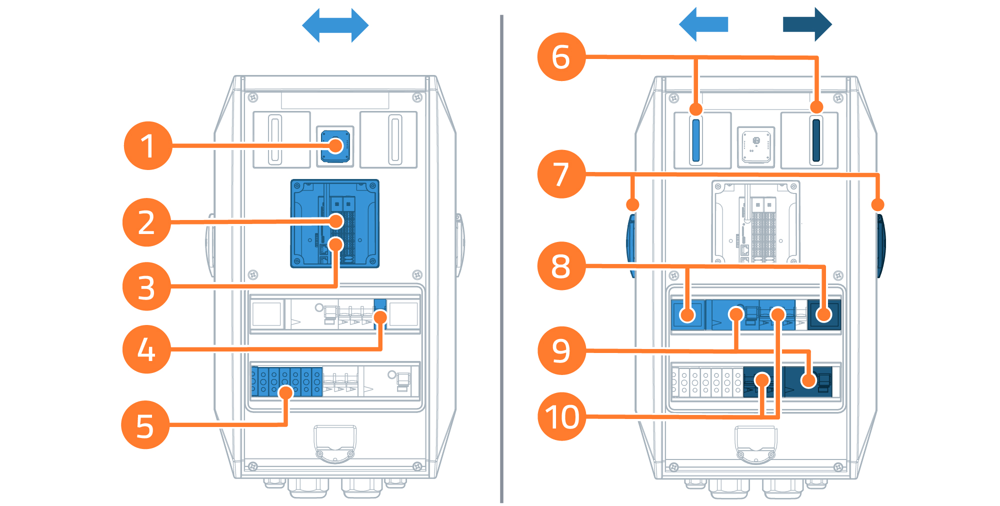
- Optional RFID reader
- Charging controller
- Data cabling interface
- Short circuit protection for controller
- Power Terminals
- LED
- Type2 socket
- Energy meter
- AC residual current protection
- Short circuit protection for charging outlets
Dimension drawing
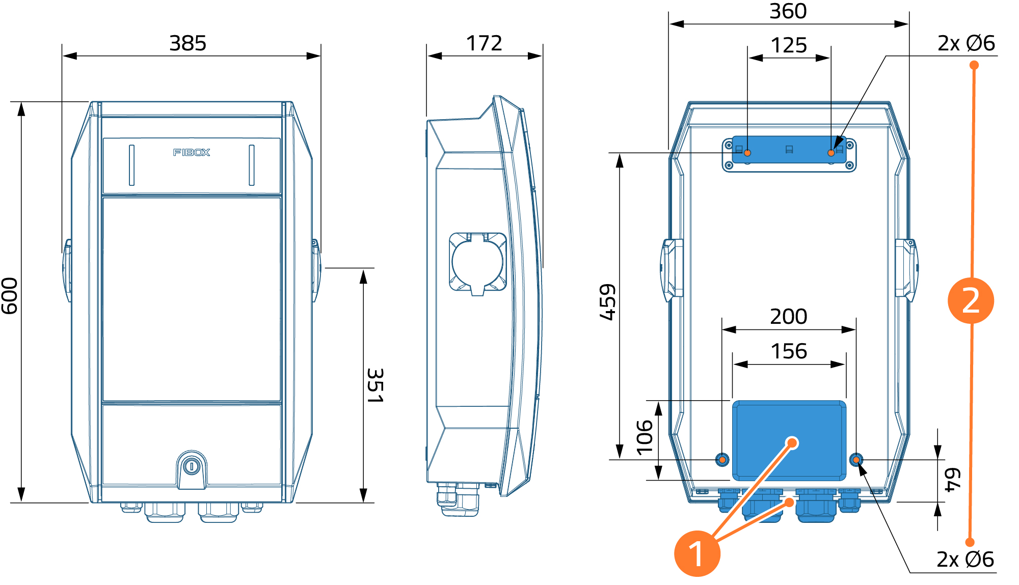
1. Cable inlet in back side and in bottom
2. Wall fastening dimensions
Needed tools

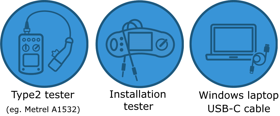
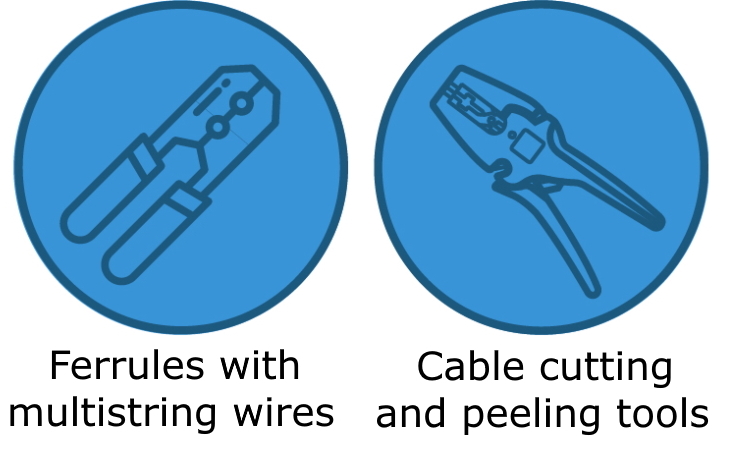
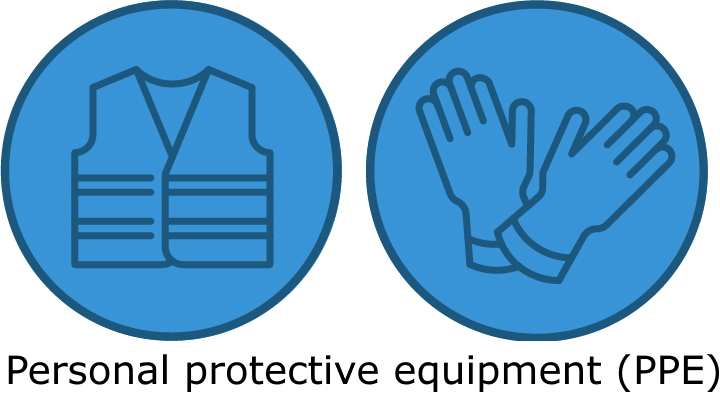
You might also need:
- In case of using thinner than 27 mm power cables, a smaller cable gland is needed
- In case of pulling cables from back side, a suitable (eg. rubber) cable gland is required
- Wrench for installing pedestal to floor anchor with bolts
Installing USB-C driver
Before configuring Fibox bluEV charging stations for the first time, you need to install proper USB-C drivers to your laptop.
To install USB-C driver, you may need admin rights to your laptop. For this reason it is recommended to install the driver prior to entering the site.
- Download USB-C driver through this link.
- Open downloads folder
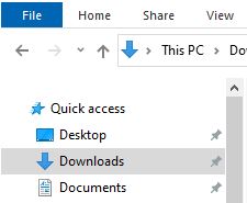
- Extract / unzip the file to a new folder on your PC
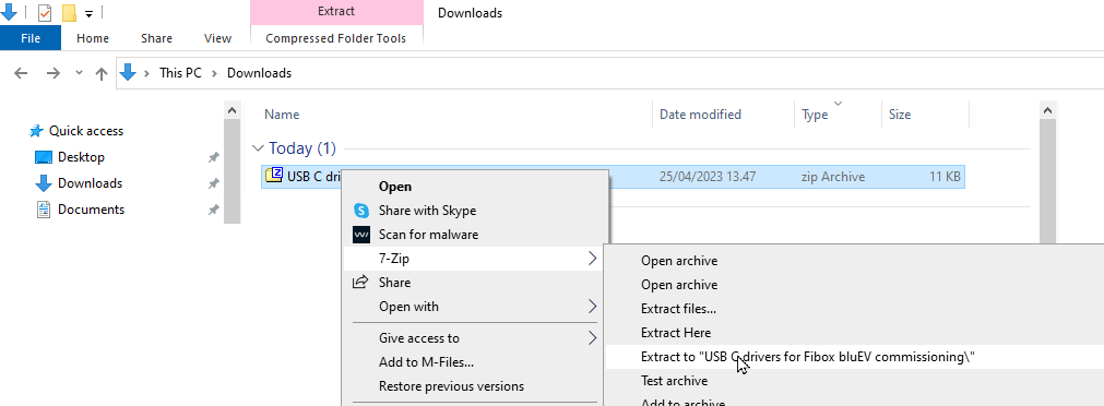
- Browse to the folder, where files were unzipped
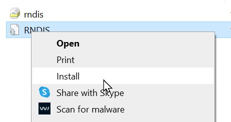
- Install by mouse right click and select “install“
Preparing the site
This chapter explains needed preparations in the site before installing Fibox bluEV chargers.
Power cabling
Multiple chargers can be daisy chained together to reduce cable usage.
| Power per socket [kW] | Nominal output current per socket [A] | Minimum cable size (copper / aluminium) [mm2] | Recommended maximum cable size [mm2] | Terminal size [mm2] |
| 11 | 16 | 6 / 16 | 35 | 50 |
| 22 | 32 | 10 / 25 | 35 | 50 |
Always size the feeding power cable respective to its protective fuse size and according to local regulations for electrical installations.
When selecting smaller input fuse than the combined nominal current of multiple chargers, charging outlets can share available current and limit current per outlet.
Installation to pedestal limits maximum cable size.
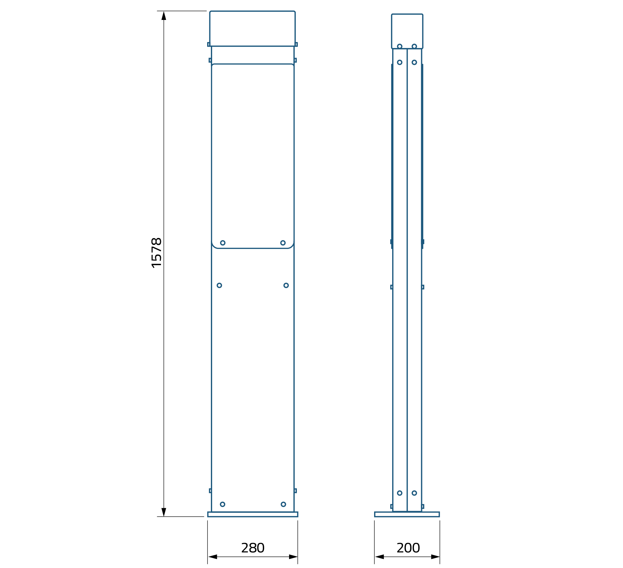
In pedestal there is one inlet with 60 mm diameter for cabling. Typically you can feed two cables up to 16 mm2 or one cable up to 50 mm2 through this inlet.
Feeding power cabling
Derive and fasten power cables. Do not mount Fibox bluEV chargers yet.
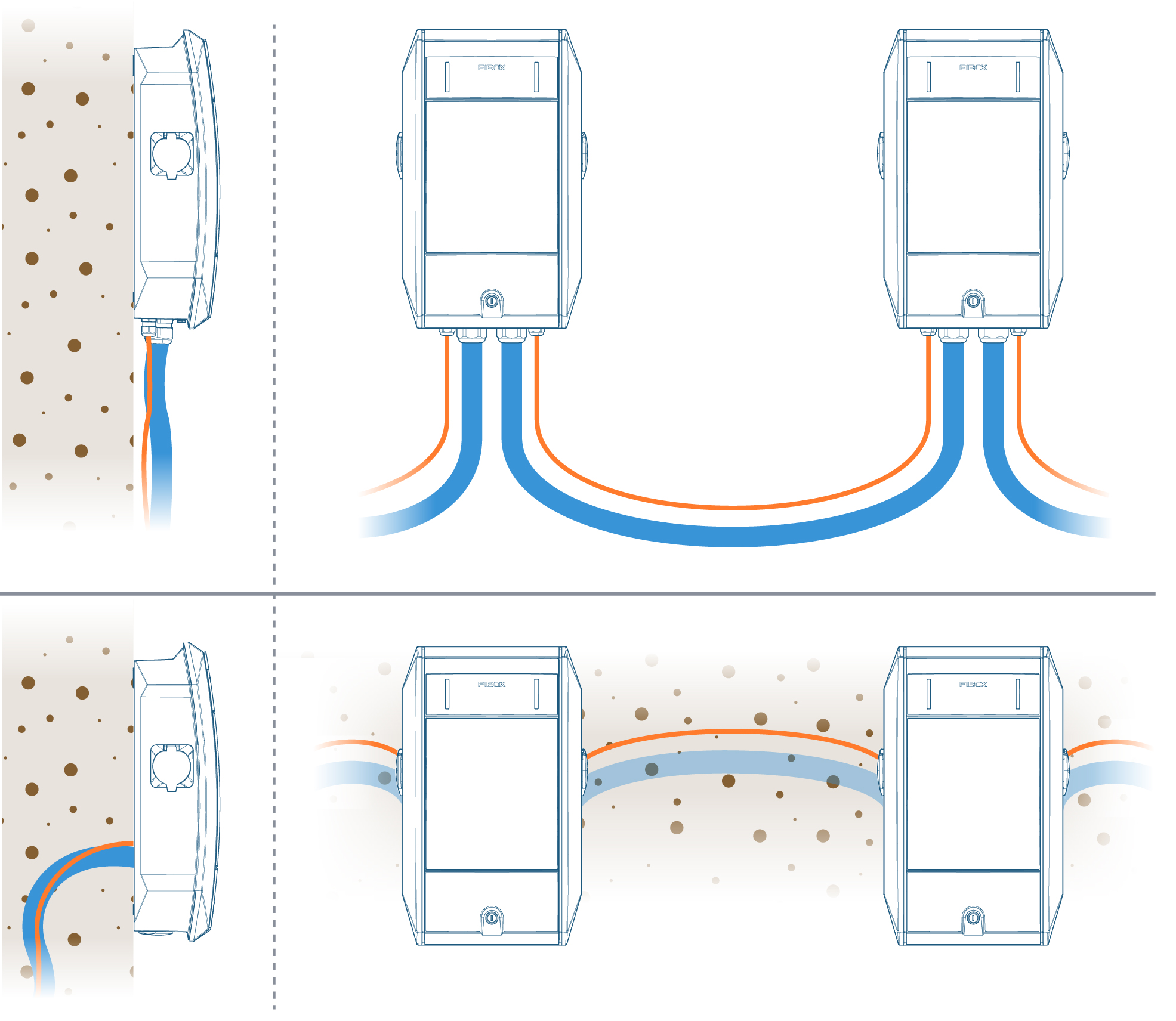
If you install to a pedestal, cables are always fed from the back side.
When feeding cables from bottom side, ensure enough space for bending rigid power cables.
Preparing power cabling
Prepare wire lengths as shown in below picture. Use ferrules with multi-strand wires.

Data cabling
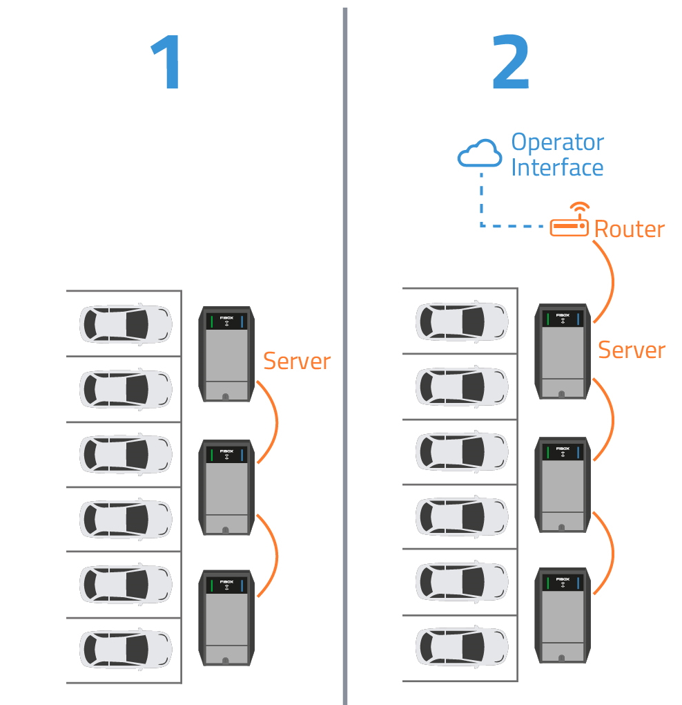
Standard method of data cabling between Fibox bluEV charging stations is chain connection using ethernet cable. Cable is chained between all chargers behind same feeding fuse/MCB.
Fibox bluEV charging station(s) can operate either
- independently in a group
- by a 3rd party Charge Point Operator (CPO) system who is monitoring and controlling chargers using OCPP protocol
Remote connection
- Independently operating chargers
- May operate without remote monitoring
- May be monitored remotely if connected to a router
- When used with operator system connecting to operator cloud can be made via
- Wired connection via ethernet
- Wireless 4G connection
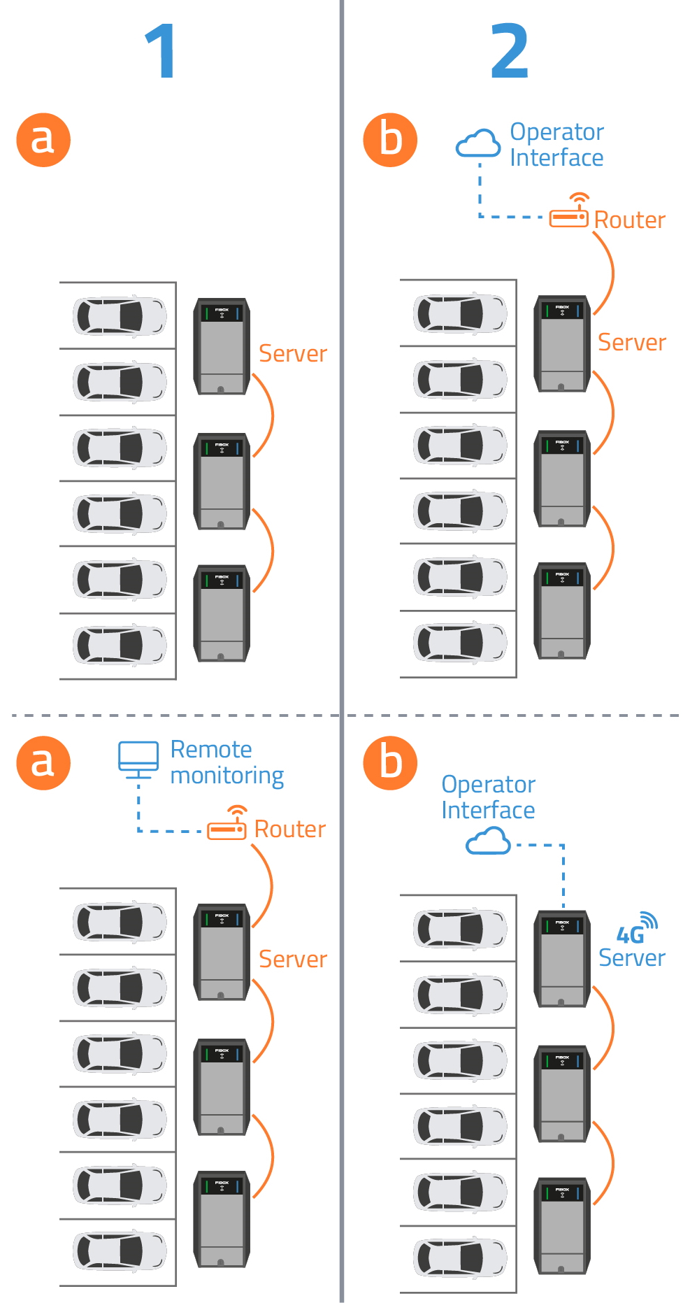
4G connection is valid for certain Fibox bluEV models and requires SIM card.
Exceptions
When specifically advised by your local Charge Point Operator (CPO), following exceptions may be considered as an option:
- a star type data connection to each unit instead of a chain
- standalone units each using 4G data connection

Feeding data cabling
Feed ethernet data cabling according to the chosen method.
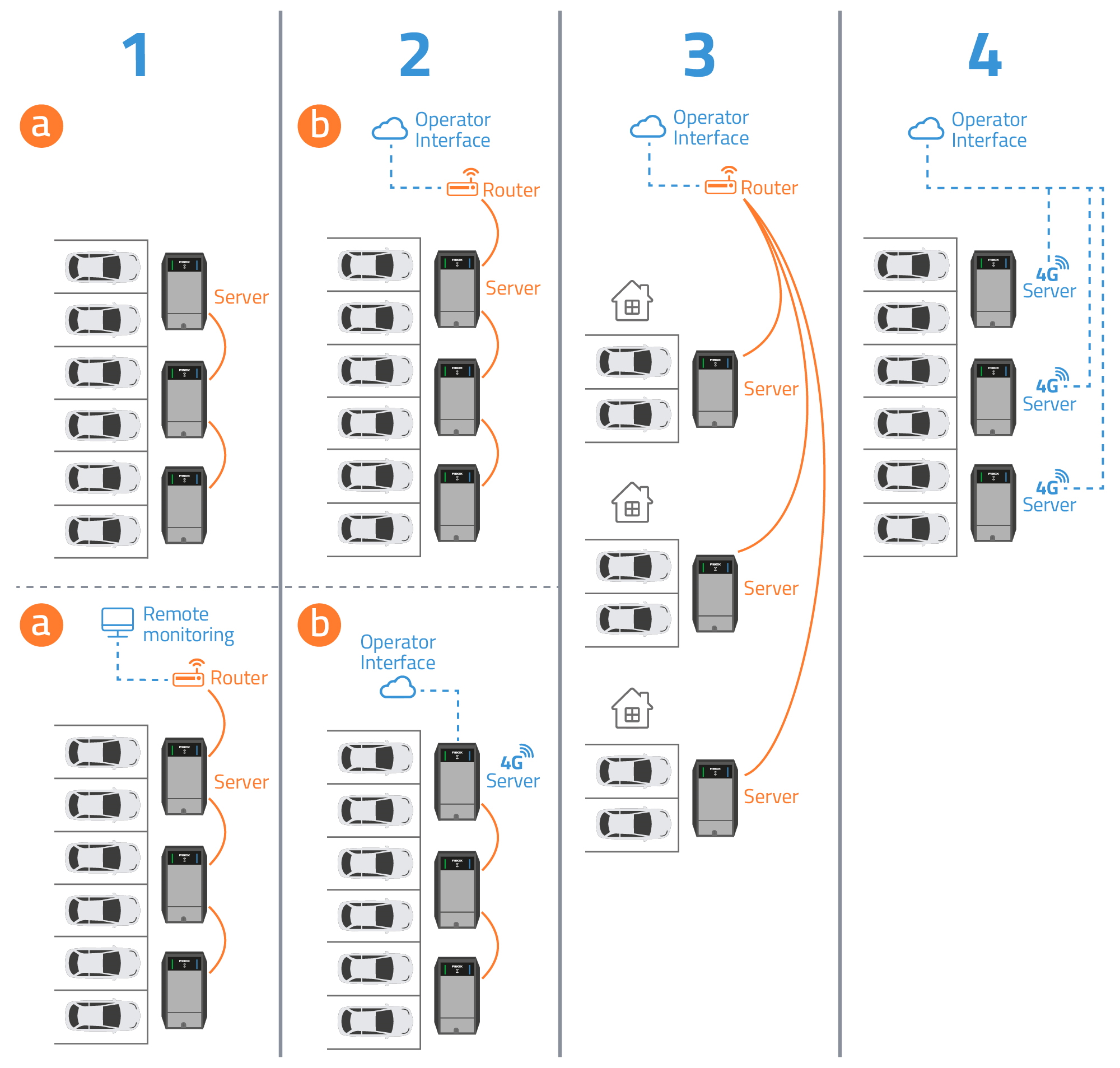
First Fibox bluEV charger in each chain is here called a “server unit”.
Server unit is used for installer to configure Fibox bluEV chargers in one chain after installation and testing, when
- installing Fibox bluEV chargers to a new installation
- adding new Fibox bluEV chargers to an existing installation
Installation to pedestal
Pedestal can be mounted to an existing 60 mm pole or to ground
Installation to ground
- Install floor anchor 3469068 to ground and feed cabling through it.
- Bolt floor mounting plate 3469048 to floor anchor and feed cabling through it
Bolts to floor anchor are not part of delivery

Installing pedestal
Assemble pedestal around the pole (screws to assemble parts to gether are part of delivery)
Rain cover and info plate on top are delivered separately as options.

Installation to wall
Ensure charger has flat and solid wall available for mounting.
If necessary, drill holes for mounting screws (4 pcs) in advance using the installation template found in the packaging material.
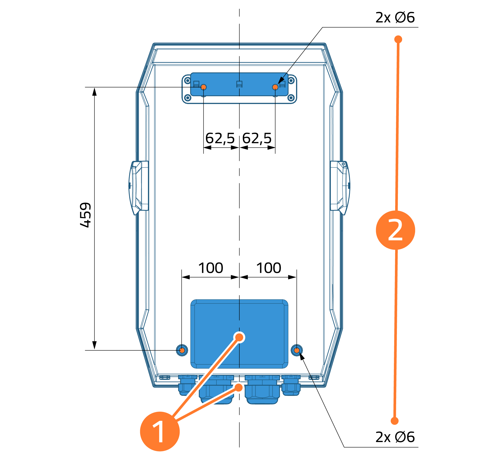
2. Wall fastening dimensions
Installation
This chapter goes through installing, mounting and cabling Fibox bluEV chargers.
Make sure the power supply of the feeding power cable to the charging station is disconnected and secured before starting the installation.
Only qualified electricians are allowed to install Fibox bluEV.
Unpacking
Fibox bluEV is packed in recycleable cardboard which contains:
- Charging station
- Password label for configuring the charging station
- Wall fastening profile
- 2 pcs 50mm cable glands
- 2 pcs 50mm screw plugs
- 2 pcs 50mm plastic nut
- 2 pcs 20mm cable glands
- 2 pcs 20mm screw plugs
- 2 pcs 20mm plastic nut
- 2 pcs rubber screw plugs
- 2 pcs of service lid keys
- 2 pcs RFID cards (optional)
- 4 pan head screws for wall installation
(screws for pedestal installation are delivered together with pedestal)
Opening the covers
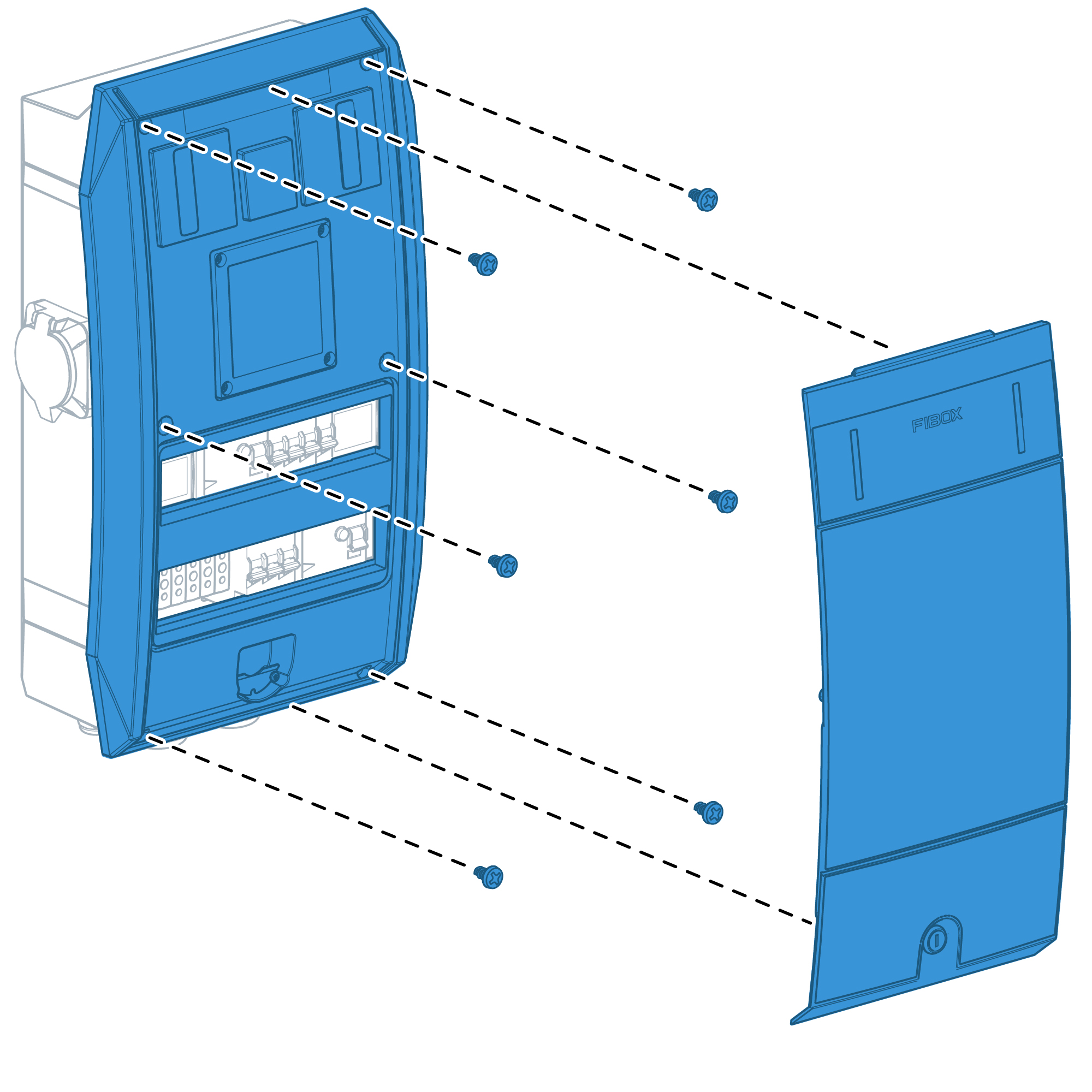
- Remove service lid using key
- Remove front cover using screwdriver
Preparing for cabling from back
- Drill opening for cables fed from the back side.
- Install suitable cable gasket (not part of delivery)
- Close the unnecessary holes in bottom side with screw plugs.
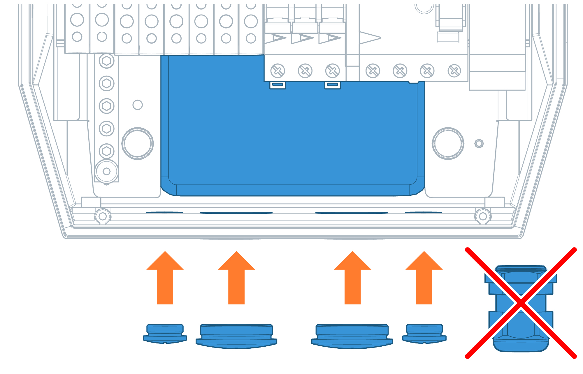
Preparing for cabling from bottom
Install the cable glands to the holes in the bottom.
Close the unnecessary holes in side with screw plugs.
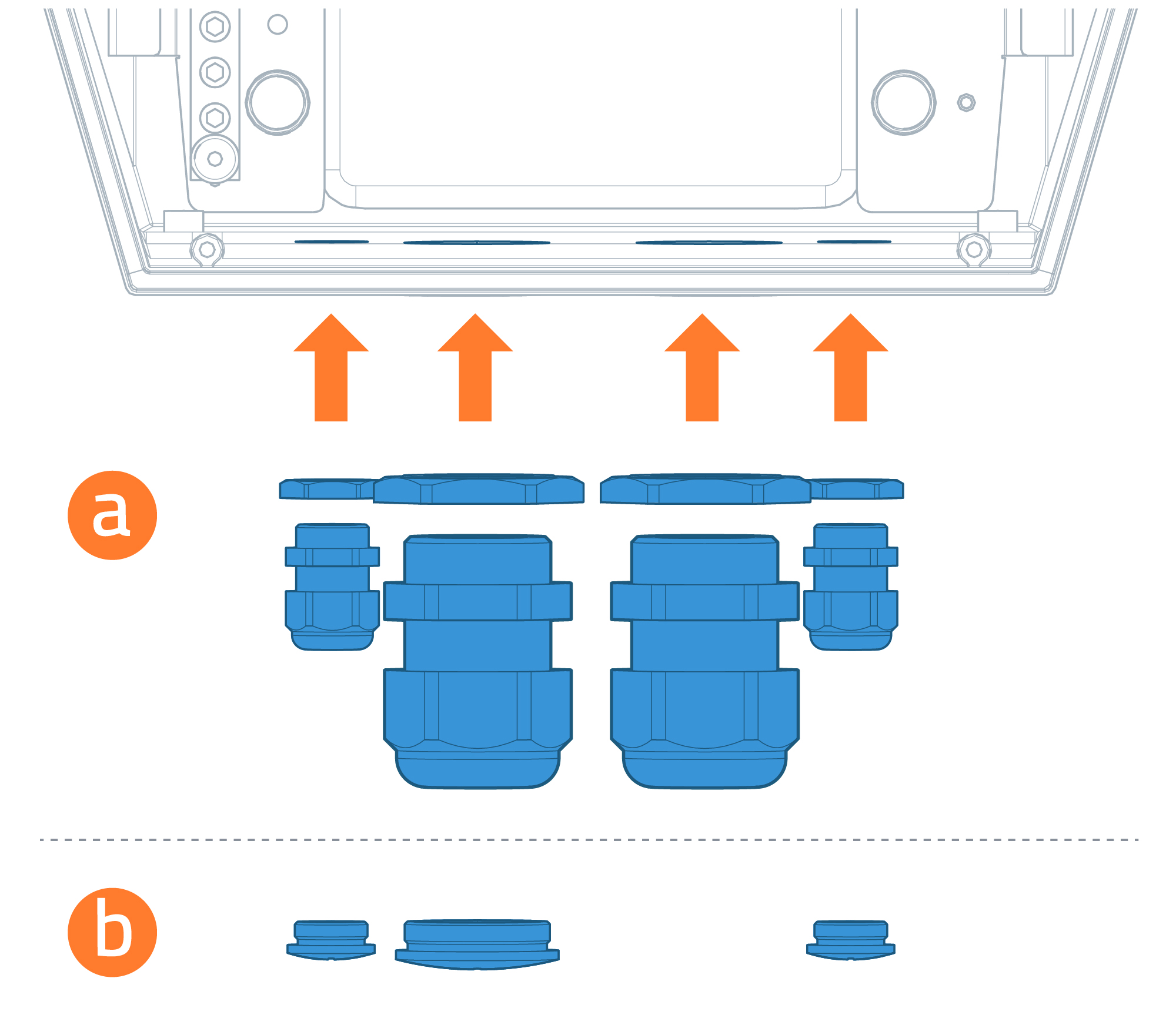
Fibox bluEV comes with openings and glands for Data and Power cabling. Power cable glands are suitable for 27 – 35 mm thick power cabling. In case of using thinner cabling use screw plugs to block the openings and install smaller cable glands (not part of delivery)
Mounting
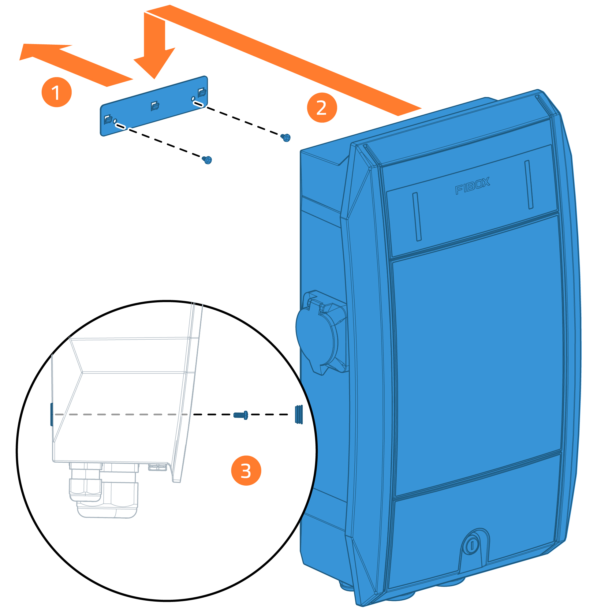
- Mount wall anchor using screws delivered with the product or with the pedestal
- Insert Fibox bluEV charger to the wall anchor. In case of installation from the back, pull cabling from the holes made earlier.
- Install screws in the bottom corners and cover them with screw plugs
Fix cabling
Pull in cables and tighten cable glands.
To ensure easy and smooth configuration of the units, it is recommended to install all units in chain before continuing to testing and configuration.
Power cabling
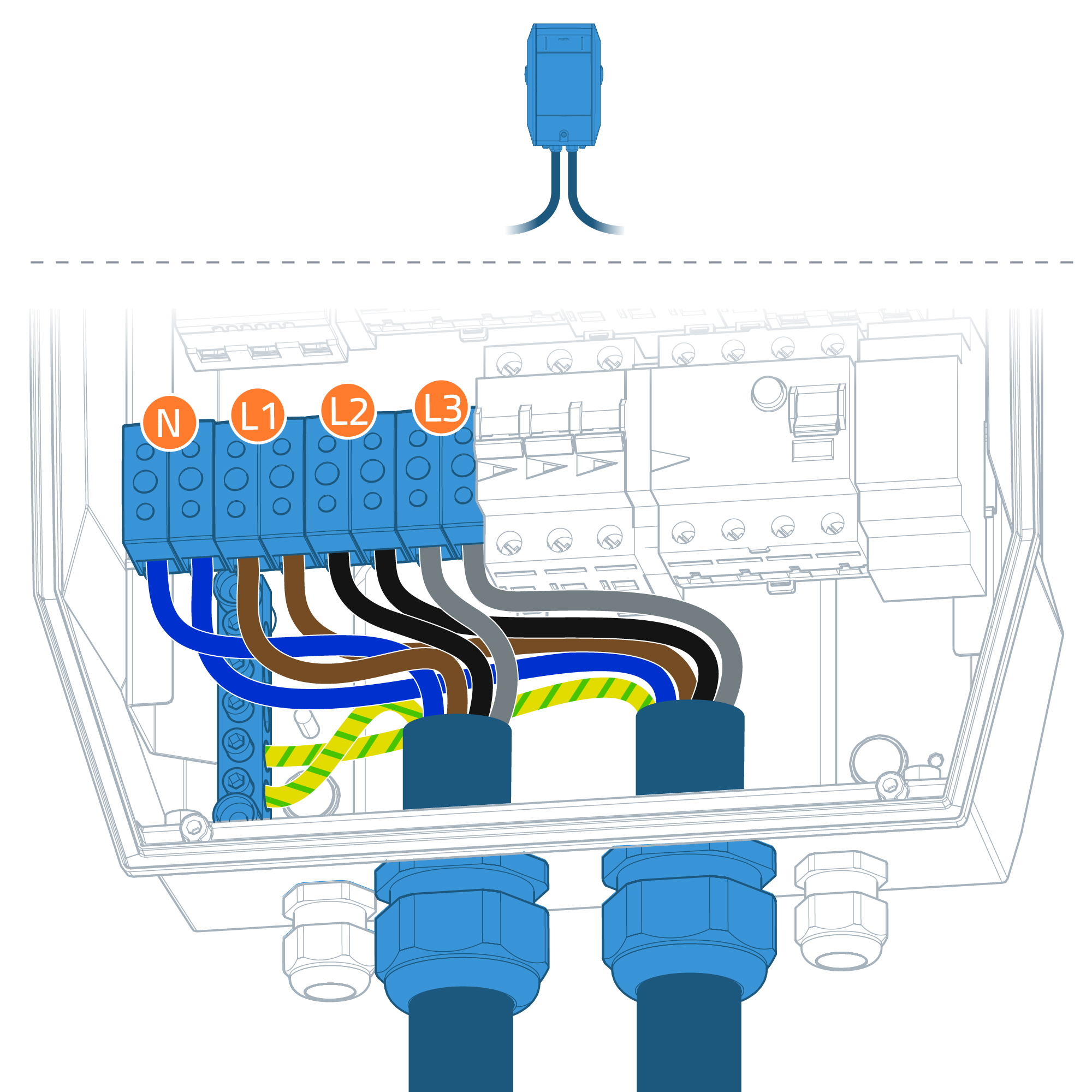
It’s recommended to install power cabling with phase rotation between charging stations.
Follow closely the phase orientation in each charger
First Fibox bluEV in chain
Connect incoming/outgoing power cables.
Connect PE wire first then continue to N and to phase wires.
Max torque setting for all screw connections is 10 Nm
Second Fibox bluEV in chain
Connect incoming/outgoing power cables.
Connect PE wire first then continue to N and to phase wires.
Max torque setting for all screw connections is 10 Nm
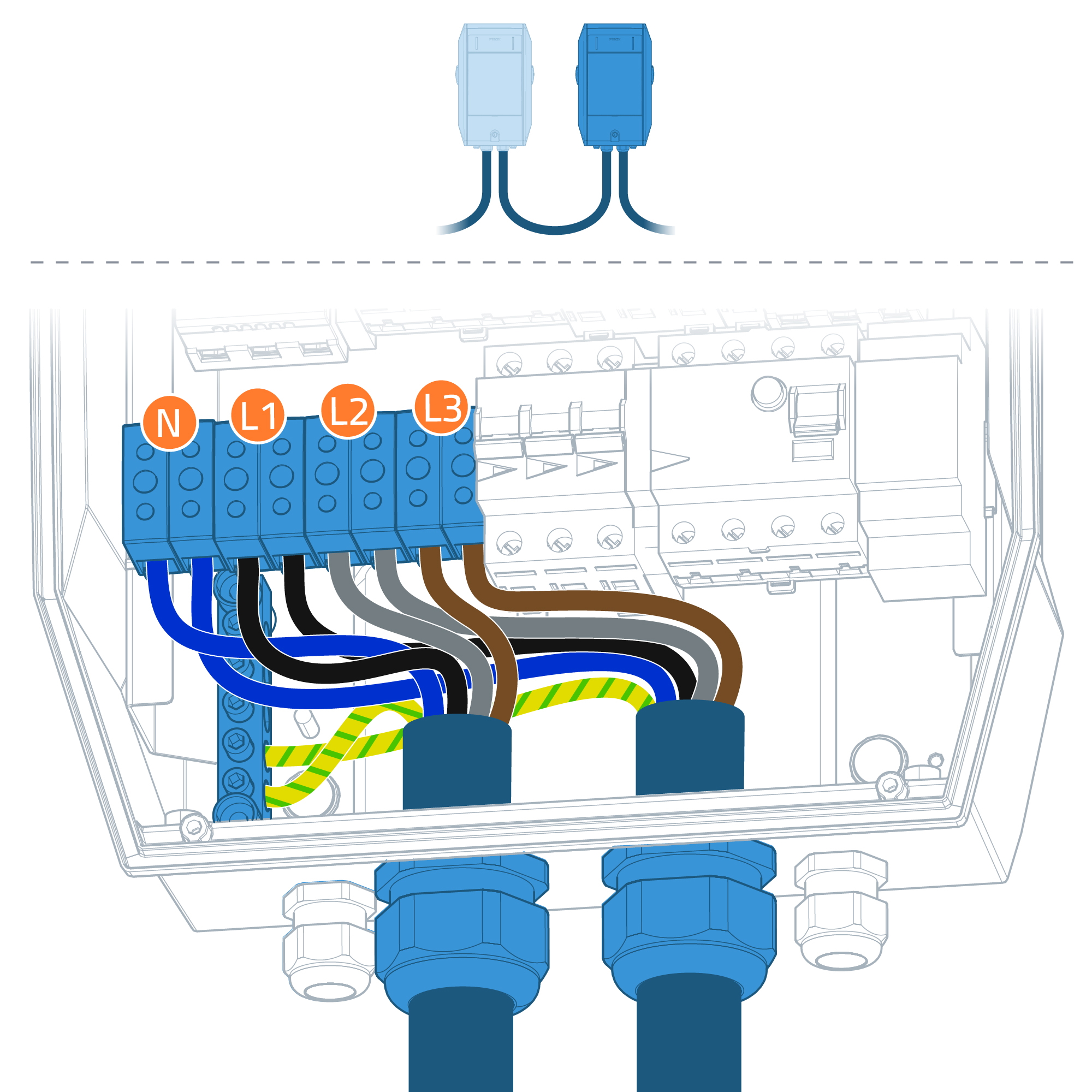
Notice different phase orientation between first and second charger.
Third Fibox bluEV in chain
Connect incoming/outgoing power cables.
Connect PE wire first then continue to N and to phase wires.
Max torque setting for all screw connections is 10 Nm
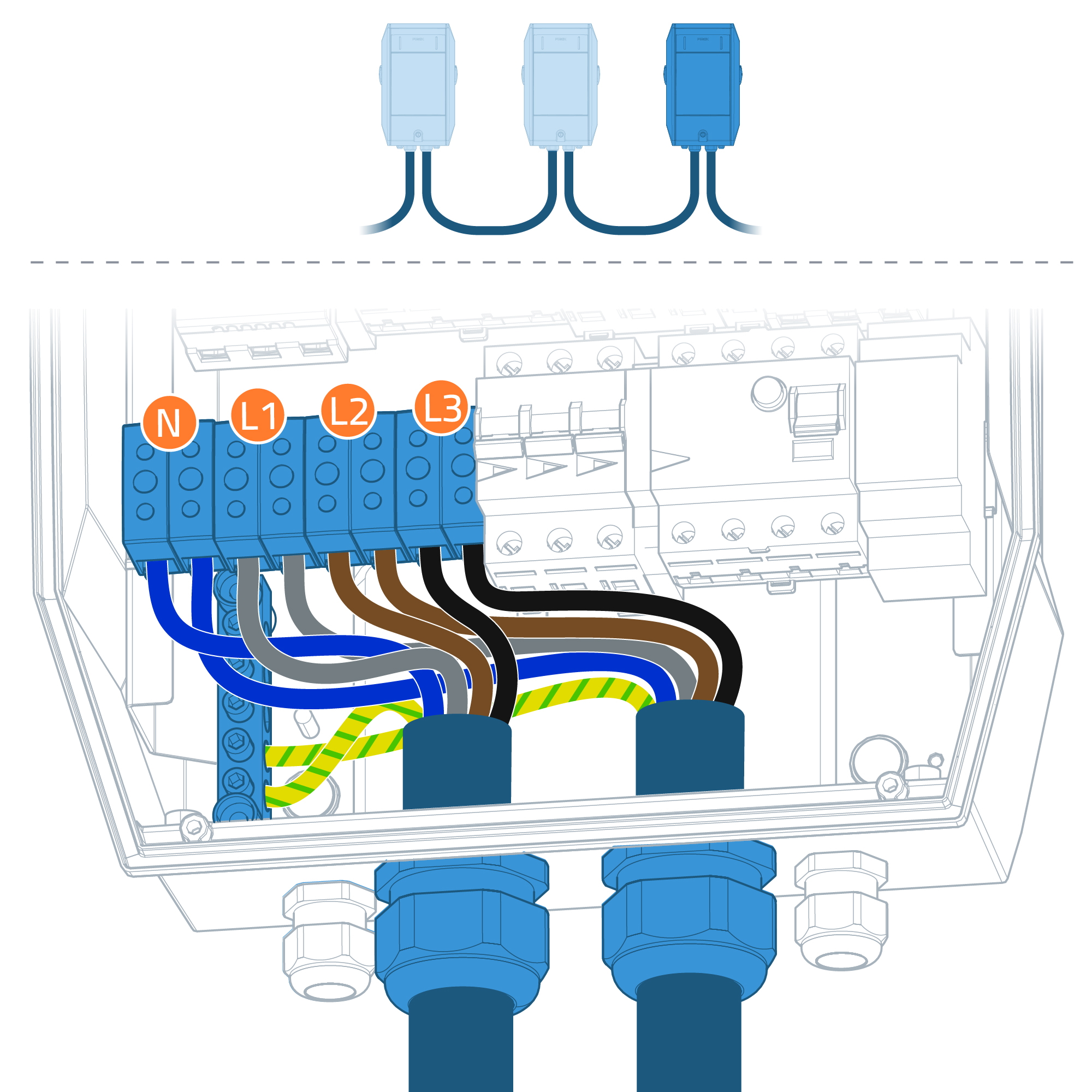
Notice different phase orientation between second and third chargers.
All chargers in chain
Continue installing Fibox bluEV chargers. Ensure that their phase orientation follows below guidance.
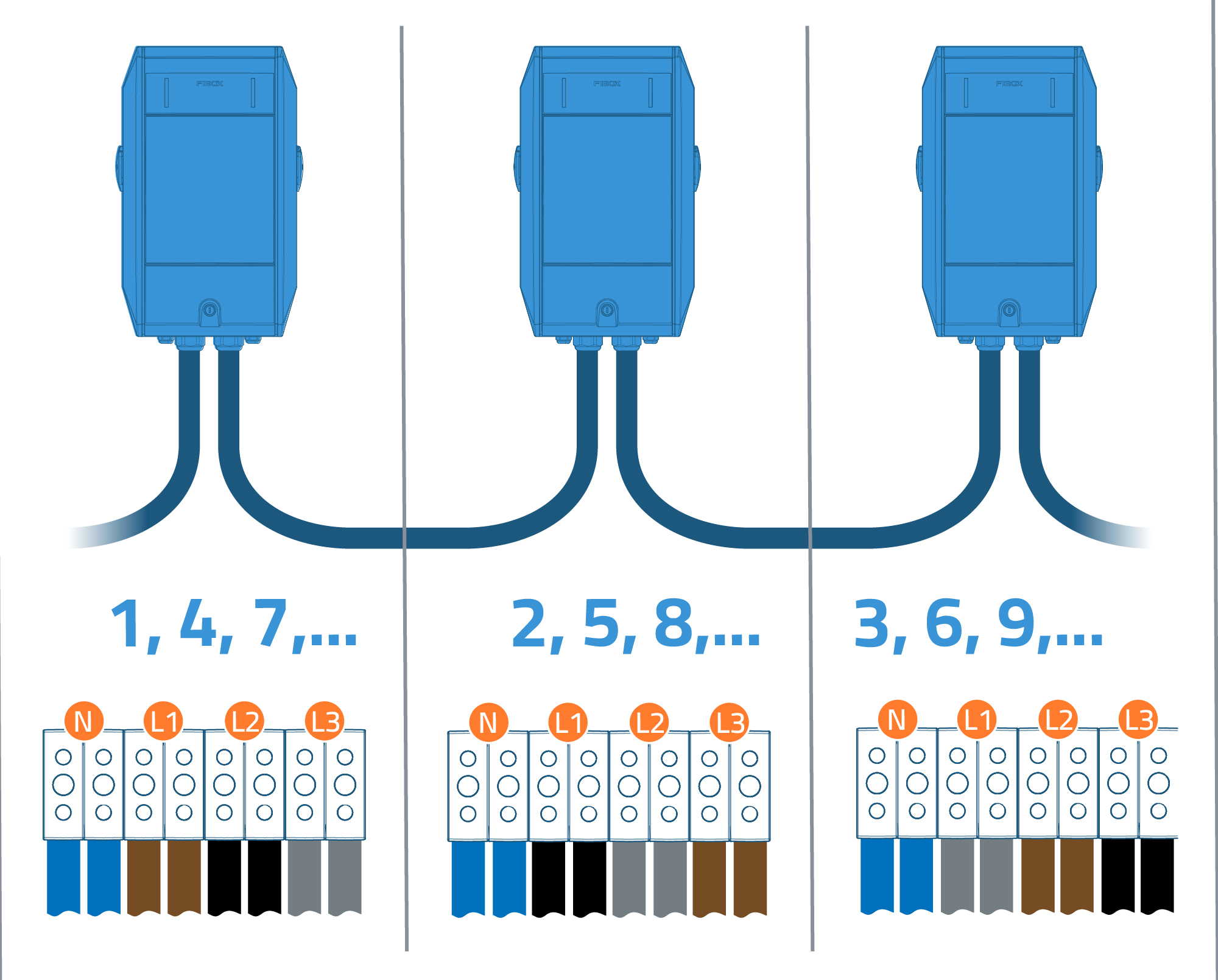
Data connection
Choose the next step depending of the used data connection type.

Ethernet cabling
Start installing ethernet cabling with the server unit.
- Connect optional ethernet cable between router and lower ethernet socket (ETH0) of the first unit.
- Mark the server unit
- Connect ethernet cable to the upper ethernet socket (ETH1) of the first unit.
- Connect the other end to the lower ethernet socket (ETH0) of the second unit.
- Repeat steps 3 and 4 between the rest units in the chain.
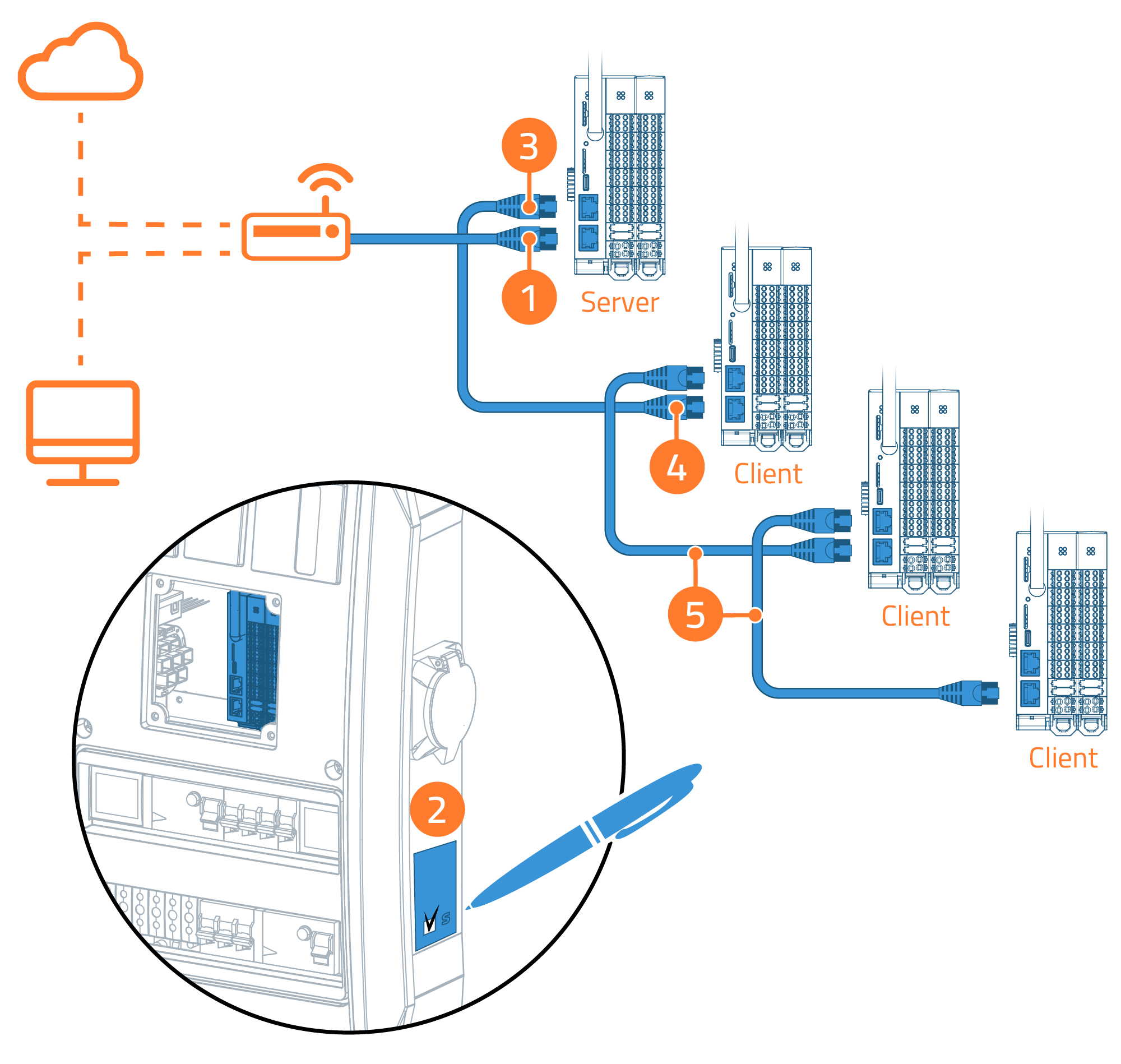
SIM-card
- Insert the SIM card into the slot as far as it will go pressing gently.
- Mark the server unit.
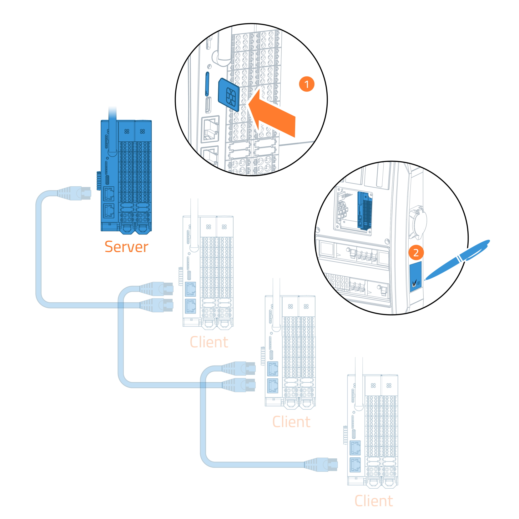
Your local Charge Point Operator may have provided you one SIM card or a card per each Fibox bluEV charging station. You can install SIM card to Server units (first of the chain) if they have SIM card slots.
Finishing installation
To ensure easy and smooth configuration of the units, it is recommended to install all units in chain before continuing to testing and configuration.
Testing
Only qualified electricians are allowed to test Fibox bluEV.
Perform electrical testing according to local regulations.
Remember to document results.
It is recommended to perform at least:
- Ground continuity
- Insulation resistance
- Short circuit impedance
- RCD functionality
Part 1
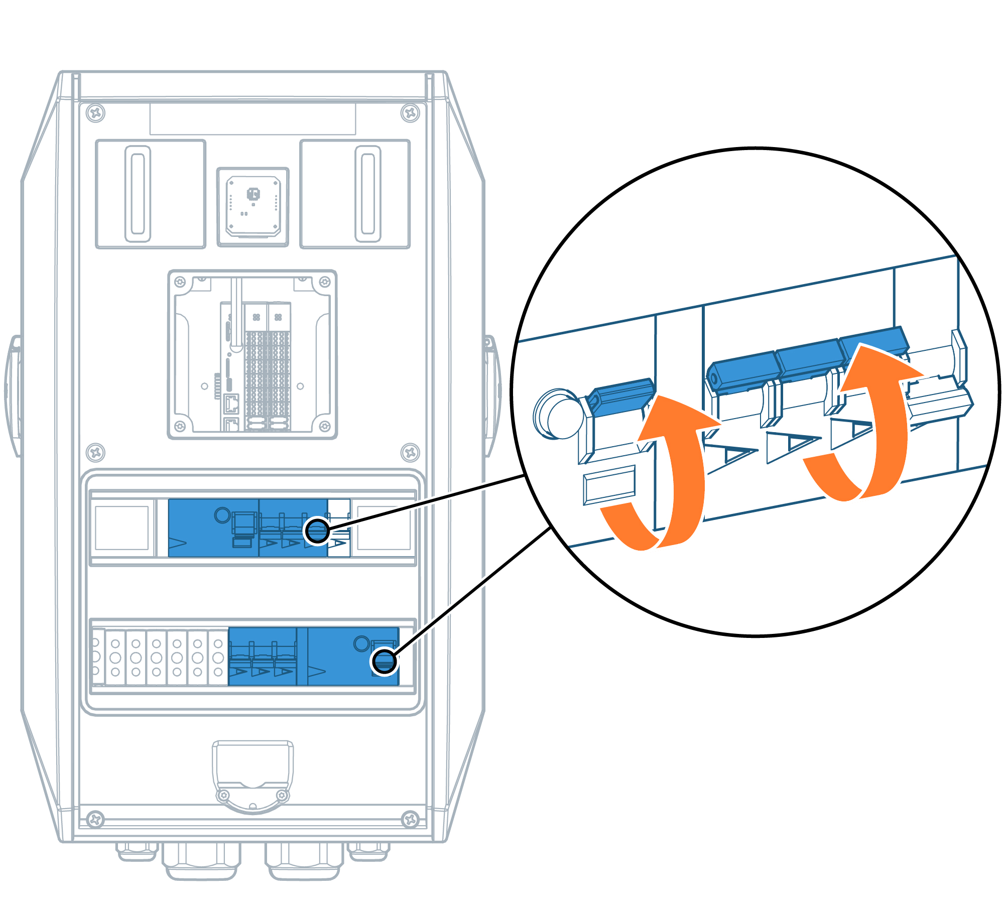
- Make sure all MCB’s and RCD’s are turned off
- Perform Ground continuity tests
- Turn on RCD’s and 3ph MCB’s
- Perform insulation resistance tests
- Repeat steps 1-4 with all chargers
Perform electrical testing according to local regulations.
Part 2
- Turn on 1ph MCB’s in all chargers under testing.

Perform electrical testing according to local regulations.
Part 4
- Perform short circuit impedance tes in each Fibox bluEV charger.
- Test RCD’s in each Fibox bluEV charger.
Perform electrical testing according to local regulations.
Part 3
- Close covers of each charger.

- Turn on power to the units from main supply
- Wait for chargers to start up and perform their self-configuration during first start-up.
Perform electrical testing according to local regulations.
Configuration
The server unit has to be configured when installing
- Fibox bluEV chargers to a new installation
- new Fibox bluEV chargers to an existing installation
Server unit is the first of each chain.
Configuration of the server unit requires a USB-C driver.
There is live voltage present in the charger when accessing the USB-C port. Configuration is allowed only for qualified electrician using proper personal protective equipment.
Installing USB-C driver
Before configuring Fibox bluEV charging stations for the first time, you need to install proper USB-C drivers to your laptop.
To install USB-C driver, you may need admin rights to your laptop. For this reason it is recommended to install the driver prior to entering the site.
- Download USB-C driver through this link.
- Open downloads folder

- Extract / unzip the file to a new folder on your PC

- Browse to the folder, where files were unzipped
- Install by mouse right click and select “install“

Connecting to server unit
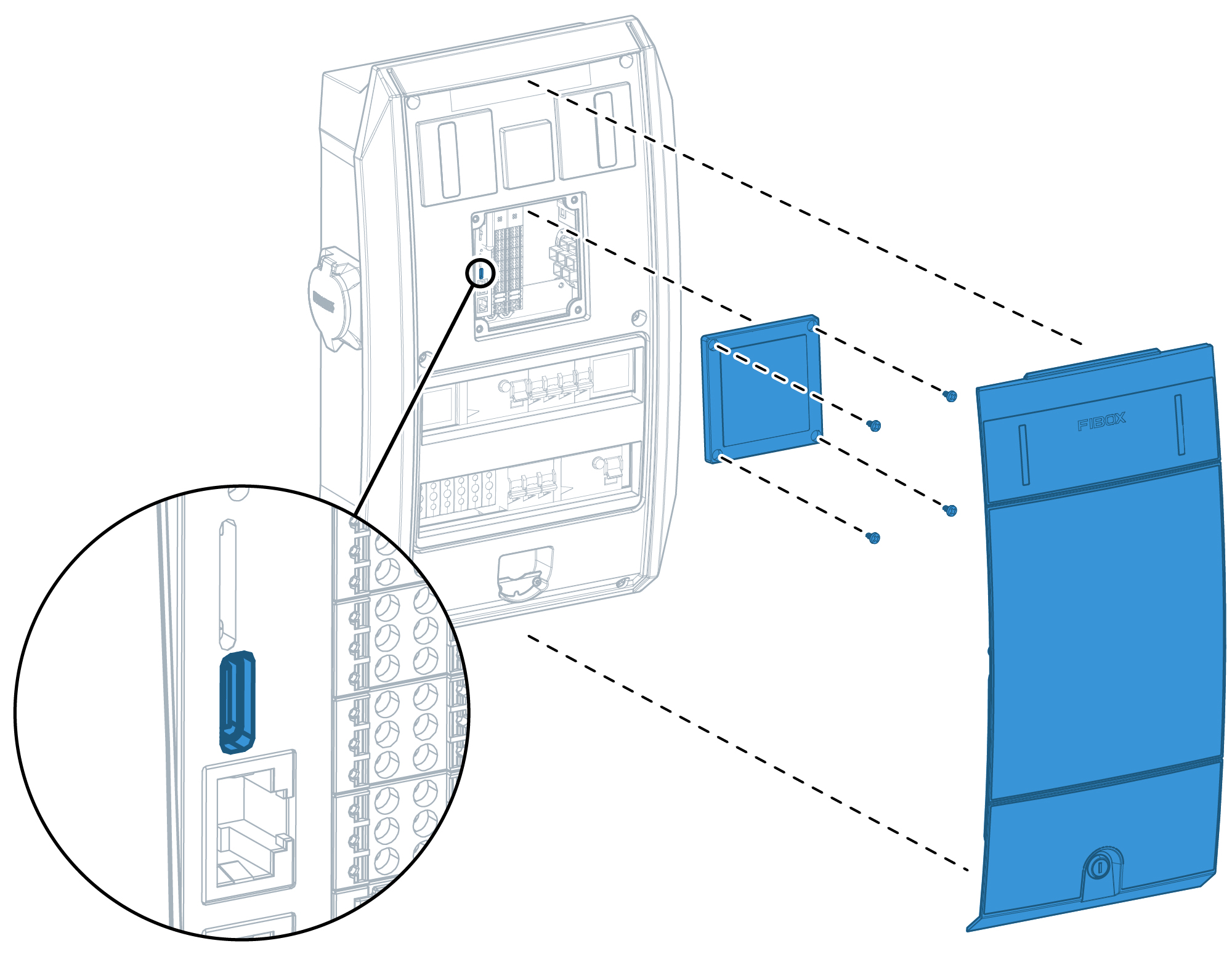
- Open the service lid of the server unit
- Open the cover in middle of the front cover
- Connect USB-C cable between the server unit and your laptop
Navigating with internet browser
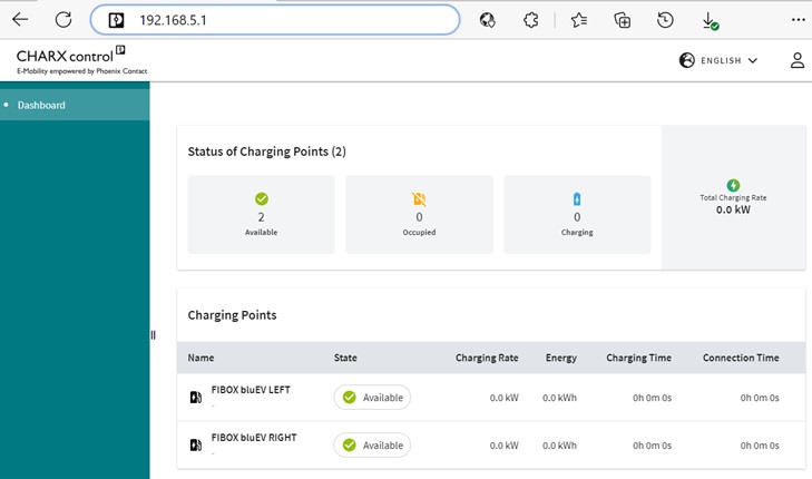
- Open web browser in your laptop
- Write address “192.168.5.1” to your internet browser and press enter
Log in
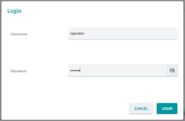
Log in as operator.
The password is provided in the password label
Overview to web interface
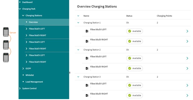
Navigate to Charging Park –Charging Stations – Overview
Navigation bar is in the left side of the interface.
You should see all installed Fibox bluEV charging stations and their outlets:
- The topmost charging station (Charging station 1) is the server unit.
- Charging stations appear in the list respective to their position in the data cabling chain.
Basic settings
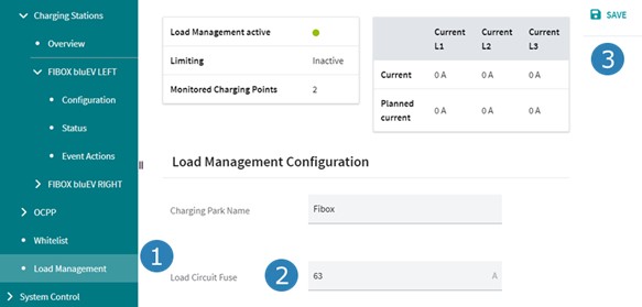
- Open Charging Park – Load Management
- Write down the fuse/MCB size feeding the charging stations
- Click “Save”
Advanced settings
The following steps may be required depending of the installed configuration
If none of the above apply to your installation, move to the last section.
Chain of chargers
These steps are required when you have more than one Fibox bluEV charging station in chain.
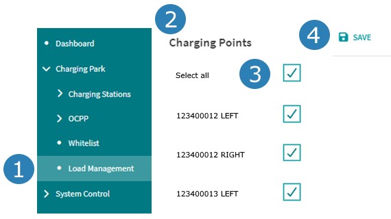
Enabling load management
- Open Load Management
- Scroll down to “Charging Points”
- Make sure “Select all” is ticked.
- Click “Save”
Phase rotation
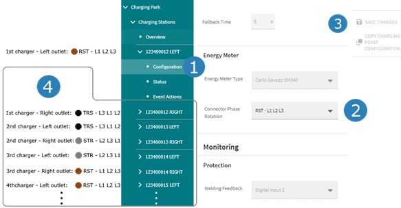
Make sure you have installed power cabling with phase rotation correctly.

Phase rotation settings
- Open Configuration of first outlet from the top of the list.
- Set Connector Phase Rotation according to the below table.
- Click “Save changes”.
- Repeat steps 1-3 for remaining outlets.
Phase rotation settings table
| Position of the charger | Connector phase rotation | |
| 1st, 4th, 7th, 10th,... | Left | RST - L1 L2 L3 |
| Right | TRS - L3 L1 L2 | |
| 2nd, 5th, 8th, 11th,... | Left | TRS - L3 L1 L2 |
| Right | STR - L2 L3 L1 | |
| 3rd, 6th, 9th, 12th,... | Left | STR - L2 L3 L1 |
| Right | RST - L1 L2 L3 | |
RFID cards
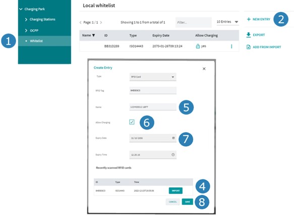
- Open Charging Park – Whitelist
- Press “New entry”
- Keep a new RFID tag close RFID reader until you hear a beep
- Press “Import”
- Name the RFID card as the charger serial number and socket side, eg. “123400012 Left”
- Make sure “Allow charging” is selected.
- Change “Expiry date”
- Press “Save”
- Repeat steps 2-8 to all RFID cards used in the chain of Fibox bluEV chargers.
Charge Point Operator
These steps are required when setting connection to Charge Point Operators cloud server.
Naming the charging park
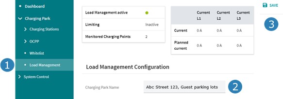
- Open Charging Park – Load Management
- Write location of chargers to “Charging Park Name”. For example address, floor level or physical location in the premises. This helps your Charge Point Operator identify the chargers when monitoring multiple charging stations remotely.
- Press “Save”
Socket identification
- Open the Configuration of the left socket of the first unit from the top.
- Name socket it using charging station serial number and position.
- Write the physical location of the charger, eg. address and parking lot number.
- Click “Save changes”.
- Repeat steps 1-4 to the remaining sockets in the list.
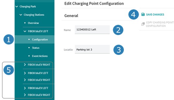
This helps your charge point operator identify the individual charging outlet when monitoring multiple charging stations remotely.
User recognition
New Fibox bluEV is set to allow users enable charging depending of model either via:
- RFID cards
- Just by plugging the charging cable
Local Charge Point Operator may control user recognition for example via their mobile app. In this case the correct user recognition method has to be set as shown below. If your Charge Point Operator doesn’t provide ways of user arecognition, these settings should not be changed.
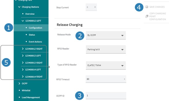
- Open ”Configuration” of first charger
- Change Release Mode to “By OCPP”
- Insert “OCPP ID”. First socket is always set as 1, the next ones as 2, 3, 4,…
- Press “Save Changes”
- Repeat steps 1-4 to remaining outlets
OCPP
- Open Charging Park – OCPP – Configuration
- In “Network Interface” drop down list, select the used connection type
- Choose “Cellular Network” if server unit has SIM card installed
- Choose “LAN – ETH0” if server unit is connected to a router with ethernet cable
3. Type the URL you have received from your local Charge Point Operator to “Backend URL” field.
Typical URL: wss://ocpp.Your_Charge_Point_Operator.com:9001/123400012
where 123400012 is a unique ID. It is recommended to use serial number of the server unit as the unique ID.
4. Press “Save”
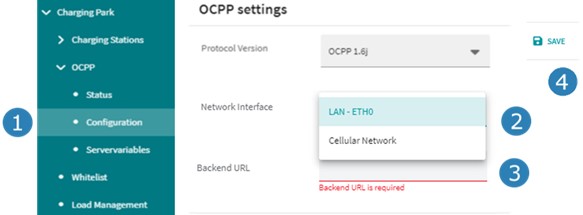
When connecting Fibox bluEV chargers to backend server for the first time, the connection must be made with unencrypted connection.
4G
- Open System Control – Modem
- Ensure “Service active” is ticked
- Type “SIM Pin” number
Check the SIM PIN number from your local Charge Point Operator or SIM card provider
- “APN value” (typical value is “internet”)
- ”Use credentials”
- “Default Route” (typically checked)
- Press “Save”
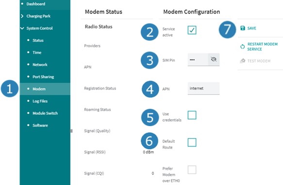
Network settings
- Open System Control – Network
- Check from your local Charge Point Operator the right status for ”No Gateway” field
- Press “Save”
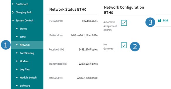
Finishing configuration
This chapter goes through rebooting the charger, testing that charger configuration is OK, and finishing installation.
Reboot
Reboot the charging station
- Open System Control – Status
- Press “Reboot system” and confirm selection
- Log back in to controller and navigate to System control – Status
- Wait until all fields are in Running status.
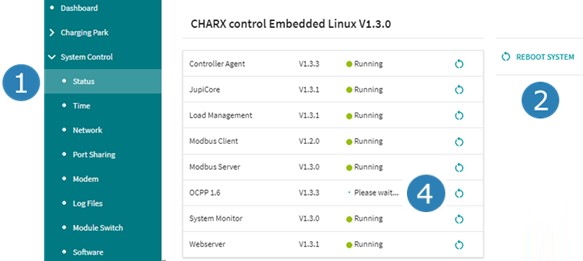
Typical waiting time:
Less than 5 minutes in case of a stand-alone unit
Less than 10 minutes in case of multiple chargers in a chain
Test
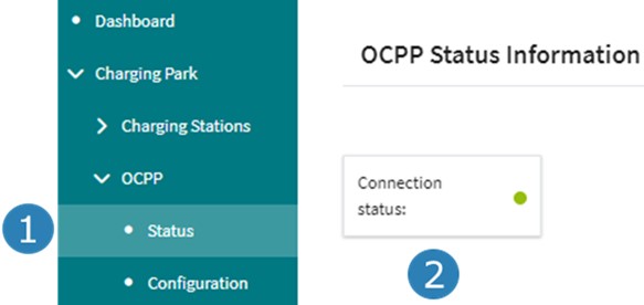
- Open Charging Park – OCPP – Status
- Check that Connection status is green
- Inform your local Charge Point Operator that the system is now set up. They should now be able to see the chain on their server.
- You may want to test remote connection with your Charge Point Operator before finalizing installation.
Disconnect and close
- Disconnect USB-C cable between the server unit and your laptop
- Close the cover in middle of the front cover
- Close the service lid

Returning loose items
You have now finished installing and commissioning Fibox bluEV chargers.
Deliver the following items to the person responsible for the chargers in premise:
- Service lid keys
- Test reports
- Password labels
- RFID tags
You can close the guide